Description #
On completion of this module participants will have a clear understanding of the physical principles behind medical ultrasound imaging. They will also be to apply this knowledge in the clinical setting to achieve optimum image quality.
Learning Objectives #
- Understand the physics of ultrasound imaging and be able to apply the physics in a clinical setting to improve image quality. This module will achieve these goals via the following specific objectives:
- Perform correct probe seletion for target structure
- Accurately adjust gain setting
- Select appropriate depth settings for target structure
- Perform correct probe positioning to enhance target structure image
What is Ultrasound? #
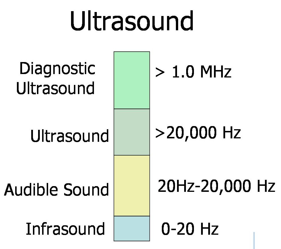
What is an Ultrasound Wave? #
It is a mechanical pressure wave in the frequency range of 3-15 MHz.
The waves are produced by ceramic piezoelectric crystals that vibrate when an electrical current is applied. The vibration emits ultrasound waves which are reflected back from the human tissues. The piezolelectric crystals then act as the receiver, generating an electric charge when bombarded by the returning ultrasound waves.
How Well Does Ultrasound Travel Through Tissues #
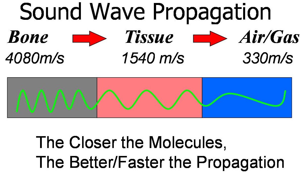
This means that ultrasound waves pass poorly through air/gas filled structures. When there is a tissue air/gas boundary, much of the wave is reflected, therefore any structures beyond the gas/air will not be seen. This is why ultrasound gel is used between the skin and the probe to improve the passage of ultrasound waves into the tissue.
Transducer Design and Transducer Types #
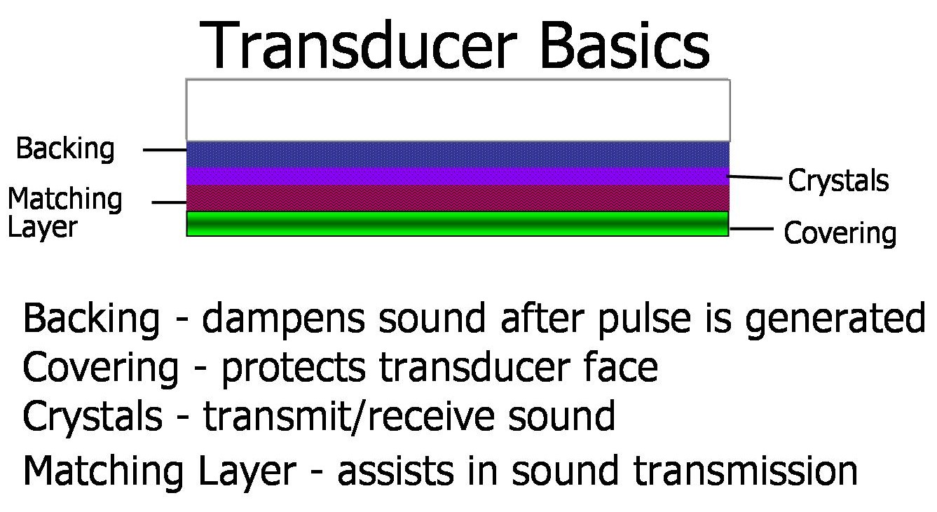
Basic Transducer Design #
The transducer is contained within the head of the ultrasound probe, and all probes consist broadly of the same components as shown below.
#
#
Transducer Types #
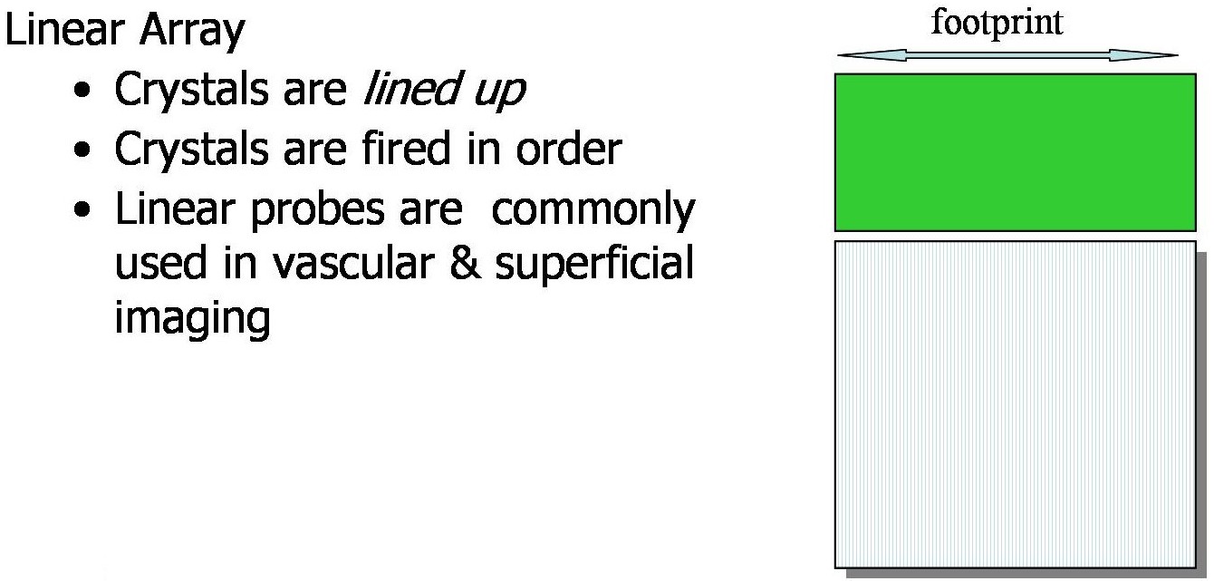
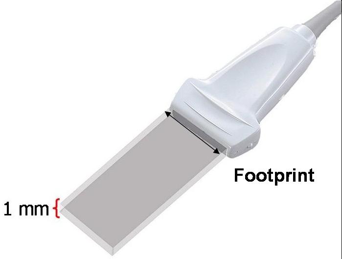
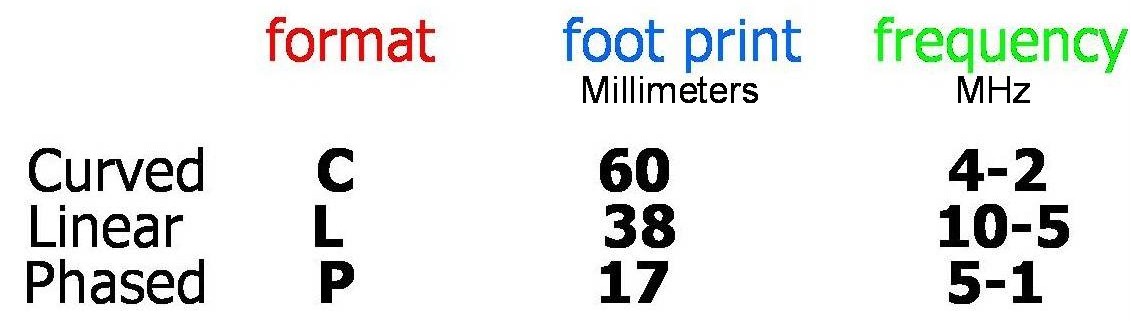
Linear Array #
The most common type of transducer used in regional anesthesia is the linear array probe. The footprint is the transducer window at the base of the probe. The linear array stimulates the piezoelectric crystals in sequence to produce a rectangular image to a specified depth. The depth of the image is determined by the frequency of the probe. The width of the ultrasound beam is only 1mm. The hockey stick ultrasound probe commonly used in pediatric practice is a high frequency(15MHz) linear array probe.
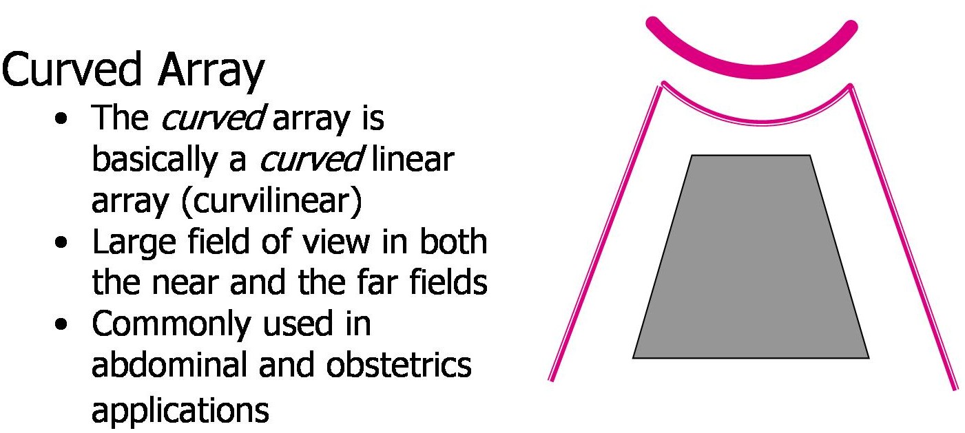
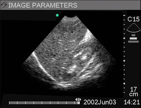
Curved Array #
This produces the ultrasound beam in the same way as the linear probe. The footprint is curved, giving a wedge shaped field of view rather than a rectangular one.
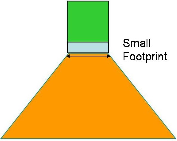
Phased Array #
The third type is a phased array which produces a wider wedge shaped window from a small footprint. This is achieved by steering and focusing the beam. This type of probe is commonly used in echocardiography.
Picking The Right Transducer For The Job #
What Type of Probe #
Suitable probes for ultrasound guided regional anesthesia are the curved and linear array probes. The vast majority of structures that are targeted are superficial and therefore easily seen with a linear probe. For pediatric practice a small foot print is required to allow needle access to the area. The hockey stick probe has been specifically designed for this purpose.
How Does Frequency Affect the Picture #
The resolution of the image increases with the frequency of the ultrasound beam. Unfortunately the trade off for resolution is penetration. As the frequency increases so the penetration of the tissue reduces, as more energy is dissipated into the tissue. If a deep structure such as the sciatic nerve is the trarget, then a lower frequency probe will be needed to penetrate to that depth. A curved array probe would be ideal. All of the common limb blocks can be done with a linear probe depending on patient habitus. The linear probe is effective up to 5-7cm depth.
Focusing The Picture #
What Happens To The Ultrasound Beam #
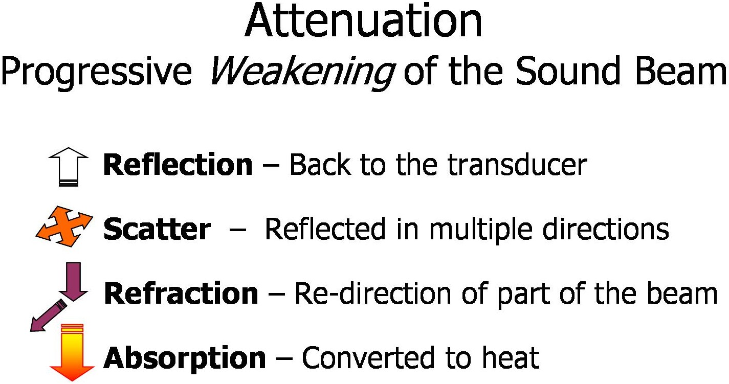
Only the waves reflected back to the transducer compose the ultrasound image. Consequently the image can become attenuated and pale if there is little reflection of ultrasound waves back to the transducer. To correct this factor the gain of the image can be altered. This increases the sensitivity of the piezoelectric crystals to the returning ultrasound waves, it does not increase the energy of the outgoing waves. The near field, far field and overall gain of the image can be adjusted.
Balancing the Picture #
The first part of focusing is to make the near and far fields a similar brightness to maintain the resolution of the whole image. Once this is done the overall gain can be adjusted to optimize brightness.
Poor Near Field Attenuation #
The probe is at the top of the screen in contact with the skin. The field closest to the trasnducer is very dark
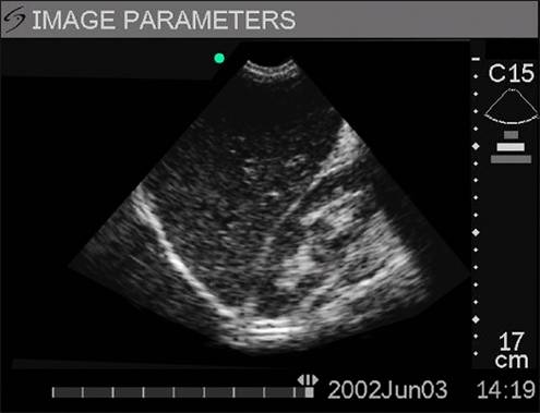
with poor resolution. Increasing the near field gain will improve the brightness and detail of this area of the image.
Far Field Attenuation #
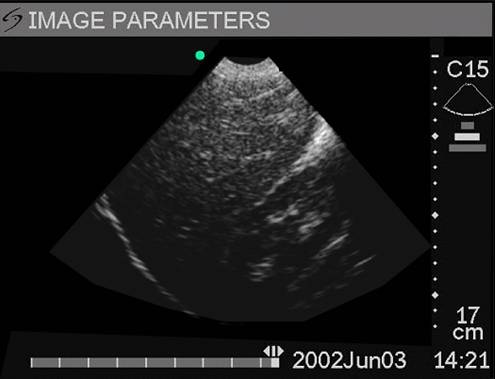
An increase in the far field gain will make the area of this image furthest from the probe brighter. These settings should be fine tuned to gain a consistent brightness throughout the image.
Balanced Near and Far Field Gain #
This will give the greatest resolution of structures throughout the whole image.
Finally the Overall gain is adjusted for image brightness #

Getting the image in the middle of the screen #
Once the correct probe has been chosen, settings on the machine need to be set to optimize image quality.
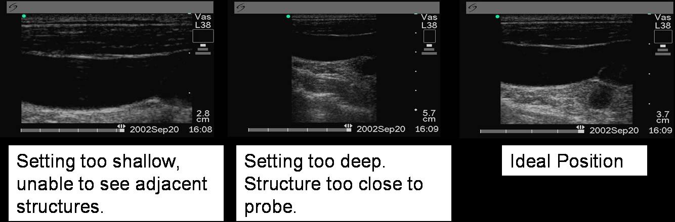
Structure Depth #
Each probe has a range of depths that can be selected on the ultrasound machine. The aim is to put the target structure in the middle of the screen to get optimal resolution and view of important surrounding structures. The depth of the image is normally displayed on the screen (here in the bottom righthand corner) and can be easily adjusted during scanning.
Choosing The Mode #
There are three basic scanning modes: general, resolution and penetration. Once the depth has been chosen, the frequency range the probe will use is set. To obtain clarity through the whole depth of the picture, both higher and lower frequencies are required. If near field structures are of interest, then the resolution setting maybe preferred, as it uses the higher frequencies. The penetration setting uses lower frequencies providing more penetration but less resolution. Broadband probes using higher and lower frequencies are designed to increase the versatility of the probe. The general setting is best for regional anesthesia as it requires both frequency ranges to give resolution and penetration.
Many machines have further settings for vascular, abdominal. thoracic or cranial scanning. These modes should be disabled in favour of small parts scanning or superficial structures.
Echogenicity #
Structures can either be Hypoechogenic (darker than surround) or hyperechogenic (brighter than surround)
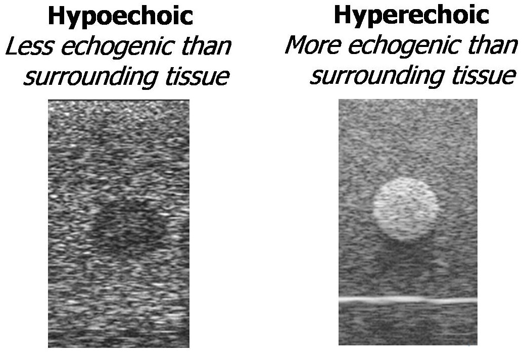
Hypoechogenic structures do not reflect the ultrasound beam back as well. If a structure is anechoic, it is black as no ultrasound waves are reflected back. This is commonly seen in vessels where the flow of blood doesn’t reflect the ultrasound beam back to the transducer.
Angle of The Ultrasound Beam #
Maximal reflection of the ultrasound waves occurs when the waves are orientated perpendicular to the target structure producing the optimal picture.The probe must be manipulated to maximize the picture.
Structures can be scanned longitudinally or in cross-section. Cross-section means that the structures are running at 90° to the probe and therefore all adjacent structures are likely to be seen.
Cross-sectional scanning the intended vessels are running 90° to the probe.
Longitudinal Scanning is where the structure is running along the plane of the probe. This technique gives no information about immediately adjacent structures and therefore is used much less commonly in regional anesthesia. The ultrasound beam is 1mm thick, therefore if this fine beam does not transect a structure then it will not be seen.
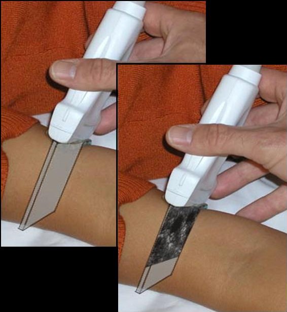
Probe Movements #
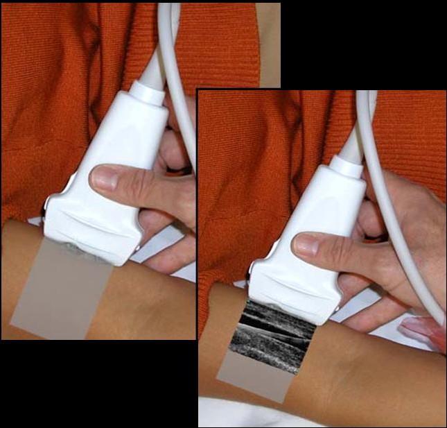
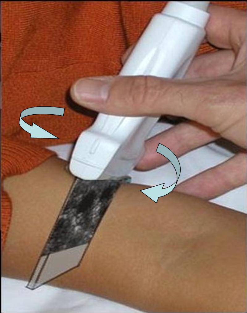
The process of scanning is dynamnic. Once a target structure is identified it’s image can be improved by subtle movements of the probe handle whilst keeping the footprint of the probe in the same place. This movement will change the angle at which the ultrasound beam is reflected back off the structure. Confirmation of structure identification is achieved by moving the probe proximally and distally following the structure to ensure that it maintains its correct anatomical relationships and path.
Toggling: Moving the handle of the probe 90° to the plane of the probe. #
Rotating the footprint of the probe to get the structure in cross-section
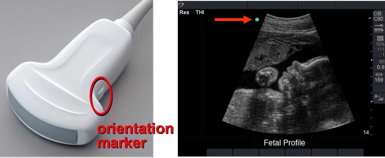
Orientation #
The probe is easily orientated with a notch on the probe corresponding to the blue spot seen on the screen. However it is important to note that the image on the screen can be inverted or flipped to produce a mirror image. To confirm orientation, always put a finger on one end of the transducer to see the corresponding area of the screen.
Ultrasound Artifacts #
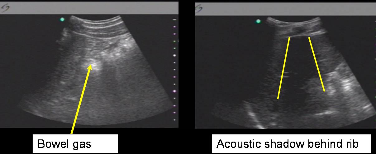
Unhelpful Artifacts #
Certain structures have ultrasound echo characteristics that are unhelpful and limit the ultrasound image. Bone reflects the majority of ultrasound waves due to it’s high calcific content producing an acoustic shadow. This makes imaging in the thoracic region between ribs very difficult. Air/gas containing structures slow the acoustic wave and also reflect much of the wave at the air/tissue boundary. This means that scanning over the bowel and lungs gives poor images and little information.
These same artifacts can be beneficial allowing identification of structures via the echogenic characteristics. When ultrasound waves encounter a low echogenic structure (e.g. fluid filled structures), there is an increase in echogenicity behind(post cystic enhancement).This gives an enhanced view of structures immediately behind the fluid filled structure. The increased echogenicity behind suggests the hypoechogenic structure is fluid filled.
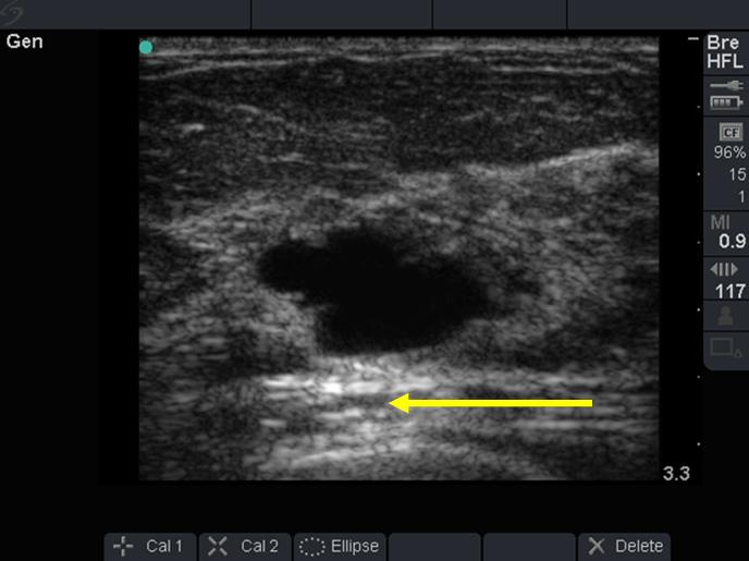
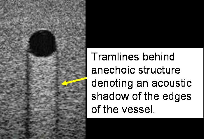
Vessels may also produce shadows related to their walls that may be helpful in identification.
How Are Nerves Represented #
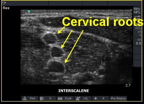
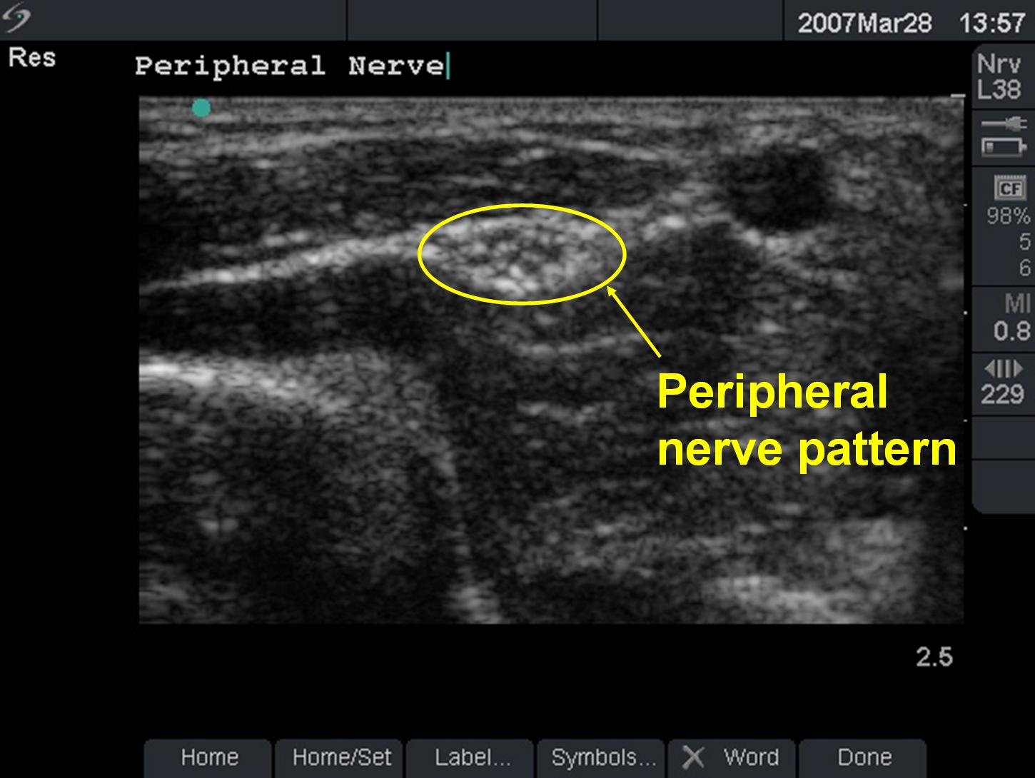
Nerves change their ultrasound appearance depending on where they are visualized in their course. If they are imaged close to the nerve root, then they are hypoechoic, as seen when imaging the nerve roots in an interscalene nerve block. As the nerves pass peripherally they become more hyperechoic. A useful nerve pattern to recognize is the multi-loculated pattern or “bunch of grapes” representing the fascicles covered by epineurium and perineurium. Identification is done by the relationship of adjacent structures and the pathway of the target structure.
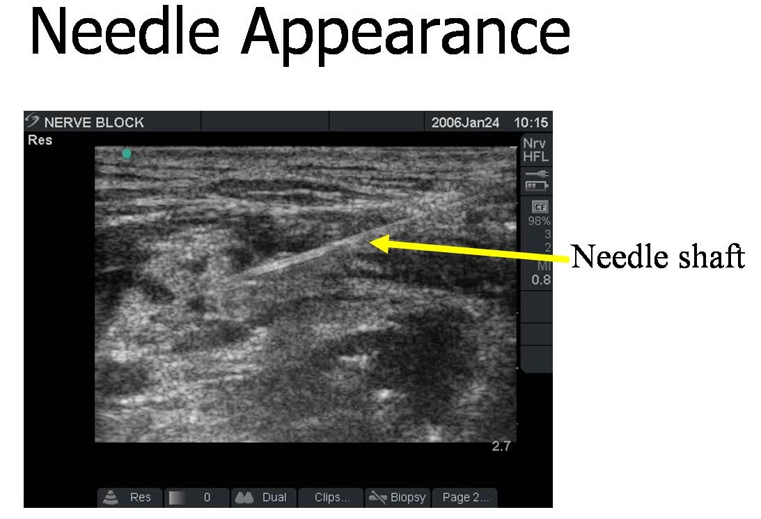
Needle Visualization #
The needle can be inserted either from one end of the probe allowing the full length of the needle to be visualized or inserted from the midpoint of the probe almost parallel to the handle of the probe. The latter technique does not allow needle tip visualization at all times and therefore is not the preferred technique. The shallower the angle of insertion of the needle, the better it is seen on ultrasound image.