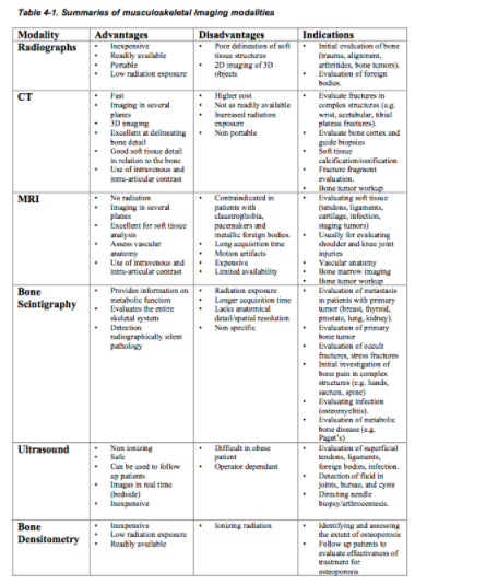
Plain Radiograph #
The Plain Film is the Mainstay of MSK radiology. Radiographs are inexpensive, non-invasive, safe, and readily available to physicians in most centres. As such the plain radiograph is almost always the initial study of choice in MSK radiology. Plain films are especially useful in the first line evaluation of skeletal pathology (fractures).
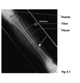
In the radiograph to the left (Fig. 4-1) you can see that the transverse fracture of the tibia, pointed out by the white arrow, is readily observed. Plain films are also excellent when trying to gather information on foreign bodies (Fig. 4-3).
Furthermore, in the workup for arthritis the plain film can provide reliable information on the bony structures and associated soft tissues (Fig. 4-2) i.e. Erosions, joint space narrowing, new bone formation (osteophytes), soft tissue swelling and calcifications are abnormalities that are not uncommonly picked up on plain films. When present, such changes can be of guidance in reaching an accurate rheumatological diagnosis.

Contrasting Tissue Types #
You may recall that there are five major densities on the plain film. In order of
increasing density these are air, fat, water/soft tissue, bone and metal. And that it is the
varying attenuation of X-rays through these different densities that gives rise to the
images we record on the cassette. Since most soft tissues have very similar densities, and
attenuation of X-ray beams is proportional to density, it can be rather difficult to
distinguish or delineate soft tissue detail on plain films.
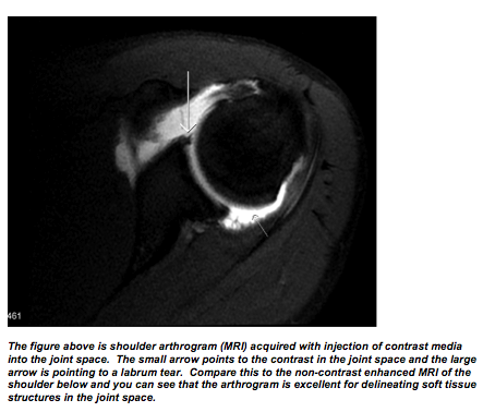
To increase the contrast resolution of soft tissue/ligaments, arthrograms are produced
with the injection of a radio-opaque contrast directly into the joint space followed by a
series of plain film studies. However, today in most centers such procedures are being
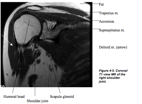
replaced with the less invasive MRI, which gives excellent soft tissue detail.

CT #
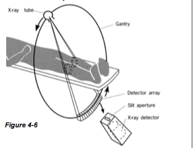
Like wise if the bone pathology (e.g. Fracture) is very small or the pathological area has density that is very similar to that of the normal bone it can be quite difficult to reach a diagnosis on a plain film.
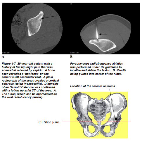
CT images can be viewed in a series of axial (transverse) slices with thicknesses from 0.6 to 10mm. In combination with the high contrast of CT images, thin slices significantly increase the sensitivity and specificity of CT imaging of the MSK systems. In particular, CT imaging is used for evaluation of bone cortex and various other cortical lesions (Fig 4-7).
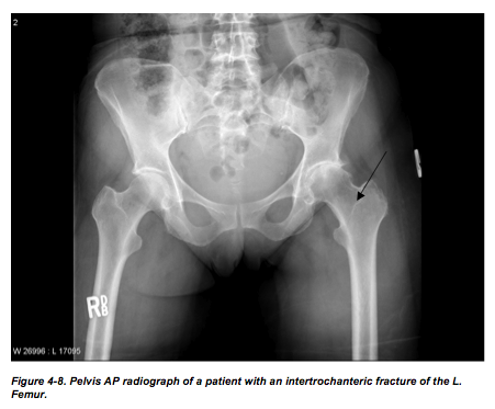
You may notice that on the plain radiograph above (Fig 4-8), it is quite difficult to fully
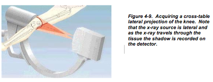
appreciate the fracture. Plain radiographs are essentially the 2D shadows of 3D structures
(Fig 4-9). When dealing with complex anatomy of the foot, spine, or femoral head (Fig
4-8), some valuable information may be hidden from one’s eyesight as the structures get
superimposed on the film. This problem is solved with CT, since it is essentially
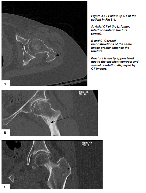
collecting 2D views of a 2D object (slices). CT is superb for the analysis of anatomical
detail and in most slices bony structures can be analyzed in relation to the surrounding
soft tissues (Fig 4-10).
With CT one also has the option of utilizing IV contrast media to acquire information
regarding the vascularity of lesions, it is useful in displaying active inflammation seen in
infections or increased vascularity of neoplasms. CT studies are also indicated in the
evaluation of soft tissue calcification/ossification.
MRI #
When your patient history and physical examination arouse your clinical suspicions of soft tissue injury, the MRI is the study of choice. As previously described in the first chapter, MRI takes advantage of the varying characteristics of protons in tissues. As the amount of water in soft tissue and surrounding structures varies, MRI has the capability to generate images with excellent soft tissue contrast. Trauma and other pathologies (inflammation, neoplasm) in general, frequently lead to changes of increased water density (mobile protons) in the affected soft tissues. Thus, it should be of no surprise that MRI studies are indicated in evaluation of tendons, ligaments, bursae, joints, meniscal tears, tumor staging.
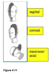
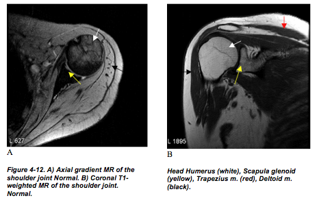
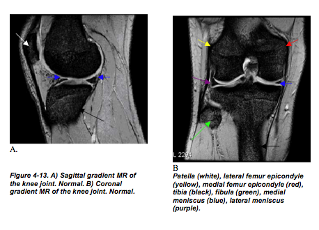
MRI also enables one to directly visualize vascular structures without the need for external contrast media. The software that is utilized in the reconstruction of MR images provides the option of viewing images in the coronal, sagittal, and transverse planes (Fig 4-11). In fact, coronal, sagittal and transverse MR images of the shoulder joint (Fig 4-12) and knees (Fig 4-13) are commonly requested to evaluate for injury.
Bone Scan #
Bone scan (or bone scintigraphy) is a versatile study performed in the nuclear medicine department. The radiopharmaceutical (tracer) that is most commonly used in bone scans is Tc-99m –methylene-diphophonate (Tc-99m MDP). MDP becomes incorporated in the mineral phase of bone and with it so does the radioactivity of the Tc-99m label which is observed via a gamma camera.
Usually, the patient is injected with 15-25 millicuries of Tc-99m MDP. After a 2-4 hour wait, approximately one-third of the radiopharmaceutical has been excreted in urine, onethird remains in extra-cellular space and one-third gets cleared out of blood by bone. At this time SPECT images and/or planar images of the patient’s skeleton can be acquired.
Uses of Bone Scan #
With an increase in blood flow and/or osteoblastic activity (or ossous remodeling) there is an increased tracer uptake. However, under normal physiology, increased skeletal bone tracer uptake may be observed at sites of high metabolism. Such sites include the sacroiliac joints and growth plates in children. It is important to be able to distinguish normal and abnormal tracer uptake on a bone scan. Abnormal uptake on a bone scan is usually secondary to tumor (primary to bone or metastatic), trauma (mechanical stress) or infection. Certain diseases present as bone scan abnormalities (functional changes) well before anatomical changes are observed on plain radiographs (e.g. bone metastasis, infection).
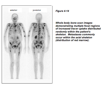
Bone scans are most often preformed to investigate whether or not a primary tumor from another organ such as the kidney, lungs, breast, thyroid gland, or prostate gland has metastasized to bone (Fig 4-14). In fact, approximately 30% of patients who have pain at the time of primary tumor diagnosis will appear normal radiographically but positive on bone scan. Keep in mind that bone scans are routinely done on ‘whole body’ basis and as such they allow you to survey the entire skeletal.
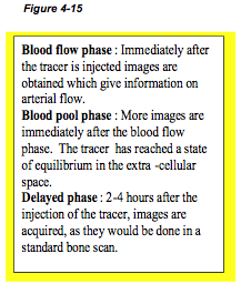
Three-Phase Bone Scan #
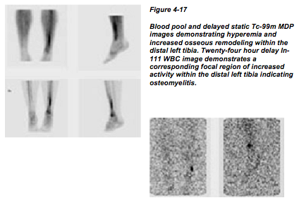
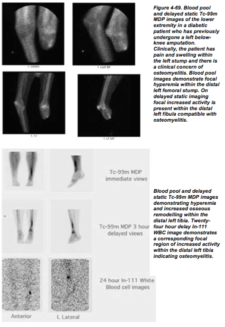
Patients with acute osteomyelitis will have increased activity in all three phases, (Fig 4-16). Bone scan changes can occur one or more weeks prior to radiographic changes in cases of acute osteomyelitis. Sometimes it may be difficult to differentiate osteomyelitis from other pathology (diabetic arthropathy or non-infected fracture) with Tc-99m MDP bone scans. Follow up scans with other radiopharmaceuticlas such as Ga-67 citrate, In-111 WBCs or Tc-66m HMPAO WBCs may be acquired and the images then compared to the Tc-99m MDP images (Fig 4-17).

Bone Scans for Preliminary Diagnoses #
When investigating a patient with unexplained bone pain, a bone scan can help determine the location or the cause of the pain as an initial study. Furthermore, when evaluating complex bony structures such as the foot, hands or spine for abnormalities on plain radiographs, it may be rather difficult to fully appreciate the abnormality (2D shadow of 3D structure). When there is clinical suspicion of pathology in such complex structures, a bone scan can be the initial study of choice to determine the location of the abnormal bone. More specific studies such as a CT or MRI of the region can then be performed in the work up of the patient.
Although the bone scan is regarded as a sensitive study it should be noted that they are not very specific. Trauma, infection, and inflammation often look similar on bone scans. To generalize, bone scans are usually ordered when a plain radiograph has failed to provide adequate information. Or, if a bone scan is utilized as the initial study, the patient’s care usually involves follow up radiograph, CT or MRI studies.
Ultrasound #
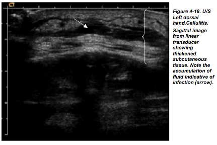
US uses sound waves (not Ionizing radiation) to generate images. US studies are inexpensive and readily available. From a musculoskeletal perspective, US is indicated for soft tissue studies and not for bone imaging. US is excellent for the detection of fluid in joints, bursae, cysts and infection (Fig 4-18). US can be used to direct the needle when performing arthrocentesis. Likewise, US can be useful when performing soft tissue lesion biopsy. When combined with Doppler, information regarding the vascularity of structures (e.g. extremities) can be collected.
Bone Densitrometry #
Bone densitometry (or bone density) is a study where the bone mineral density (BMD) is evaluated. The most common technique is the Dual Energy X-ray Absorptiometry (DEXA). By aiming two X-ray beams with different energy levels through the bone, absorption of each beam by the bone is measured and information regarding the bone mineral density of the patient is calculated. The utility of bone densitometry is in its ability to identify and assess the degree of osteoporosis. It is also commonly performed to monitor patients with osteoporosis to see how well they are responding to treatment.
Summary #
Normal Radiographic Anatomy #
In the following section we will focus on normal anatomy, particularly bones, as they appear on radiographs of the extremities. Keep in mind that it is the extremities that are constantly exposed to workplace hazards and other types of trauma. As such images of extremities are frequently requested. You must have a solid knowledge of the normal anatomy (bones and joints) to intelligently evaluate images. Furthermore, you must have a solid understanding of how and why different views (e.g. AP, PA, oblique) are generated.
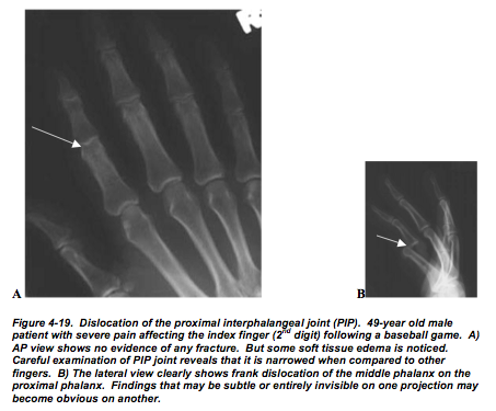
Sometimes the pathology will create very subtle or no radiographic changes on oneprojection but then it is more easily evaluated in another projection (Fig 4-19).
It is important that you keep in mind that sometimes the patient is severely traumatizedand/or uncooperative making acquisition of orthogonal views difficult if not impossible.In such circumstances it may be necessary to use cross sectional imaging like CT.
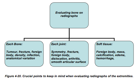
You should have a reliable system when you are evaluating upper and lower extremity radiographs (Fig 4-20). You may have noticed that each radiograph has many bones on it. Start with the bones and carefully evaluate each bone on the film for fractures, foreignbody, tumor, infection and its density. And be aware that variations of normal anatomy may be present. Next, evaluate all the joints for fractures, foreign body, signs of arthritis, dislocations, symmetry and check the smoothness of the articular surfaces. Then you must evaluate the soft tissues looking for foreign body, masses (tumor, cyst), calcification, hemorrhage, and edema. And remember to follow this routine on all the different projections (AP, oblique, lateral).
Upper Extremities #
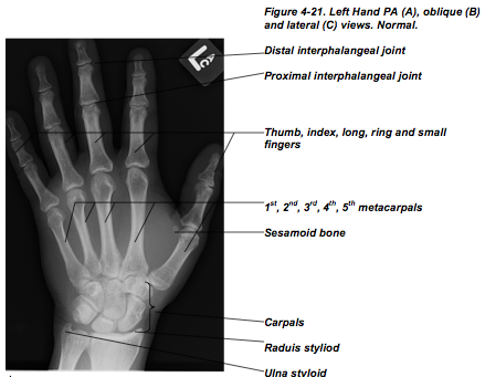
The standard radiograph of the hand usually consists of PA, oblique and lateral views (Fig 4-21). The hand is very complex structure. You must develop a good system of naming each digit so that you can accurately communicate with other members of your care team. Do not just number the digits starting at the thumb. This will be inaccurate in cases where a digit is missing (e.g. in a hand with no thumb the index finger will become 1st digit).
Always start at the radial side of the hand with the thumb (not 1st finger). Next are the index finger, long finger, ring finger, and finally small finger. This system will always yield accurate information even when digits are missing. With the exception of the thumb (two phalanges), the fingers are made up of three phalanges. Name these according to their locations as distal, middle or proximal and then name the joints in between accordingly (Fig 4-21A). The 1st metacarpal articulates with the thumb, 2nd with index finger, 3rd with long finger, 4th with ring finger and 5th with small finger (Fig 4-21A). The wrist and forearm are among the most common sites for fractures.
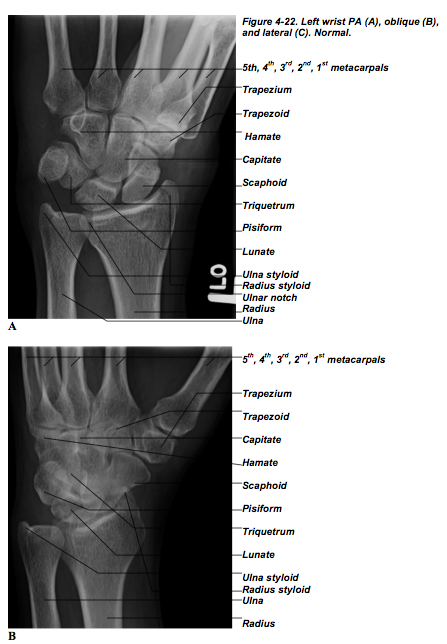
Therefore, you must have a good understanding of the carpal bones and their relations to the radius and ulna.
This can be achieved with standard PA, oblique, and lateral view of wrist (Fig 4- 22).

The Forearm, Elbow #
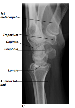
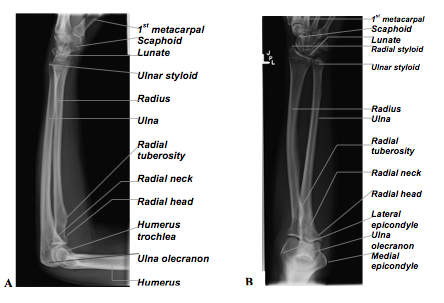
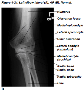
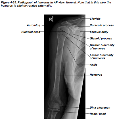
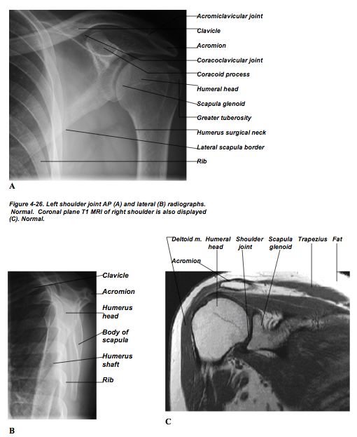
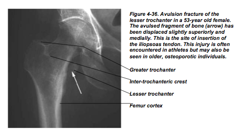
For the forearm, usually AP and lateral views are obtained (Fig 4-23). The elbow is separately evaluated on AP and lateral views (Fig 4-24). Radiographs of the humerus are obtained in AP and lateral views (Fig 4-25). The shoulder joint is well evaluated with AP view, but an axillary or lateral view can be added as well (Fig 4-26).
Fig 4-23 Below are Left forearm lateral (A) and AP (B) views. Normal.
The Shoulder #
The Lower Extremity #
Let us now turn our attention to the radiographic anatomy of the lower extremity. We will start distally at the foot and ankle joints and work our way proximally to the hip.
The Foot #
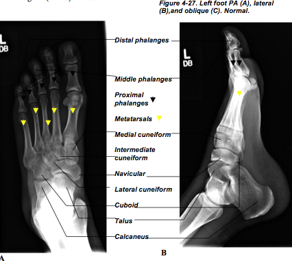
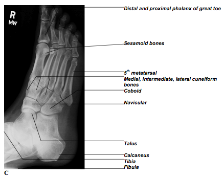
Figure 4-27 shows the usual radiographic views of the foot: AP and lateral. Again as was the case with the hands, the correct naming of the toes is crucial. Start with the great or big toe and call it toe number one. And then number down sequentially to the little (fifth) toe. Simply continue the same numbering convention in naming the metatarsals. That is the first metatarsal articulates with the great (1st toe) and so on.
The Ankle #
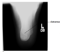
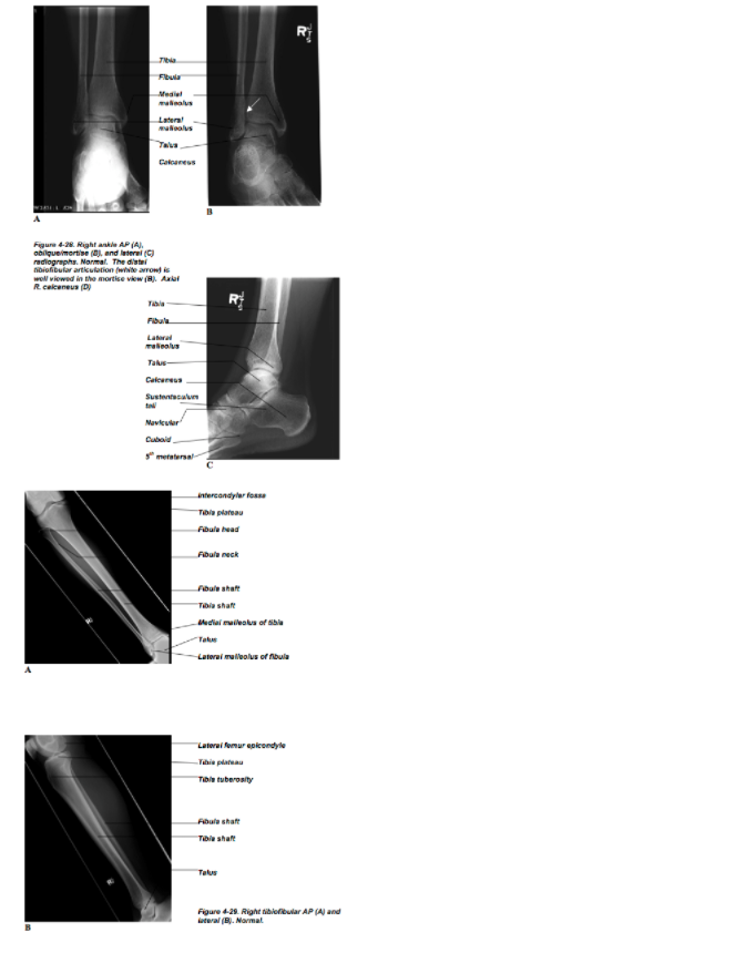
The standard views of the ankle joint are the AP, lateral, and oblique/mortise (Fig 4-28). The latter is acquired with the ankle joint internally rotated. Sometimes an axial view of the calcaneus (Fig 4-28D) is acquired. As we talked about earlier in the chapter the plain film does not give you much soft tissue detail. Therefore, MRI of the ankle joint is routinely ordered to evaluate soft tissue injury. When evaluating the tibia and fibula an AP and lateral views are usually sufficient (Fig 4-29).
The Knee #
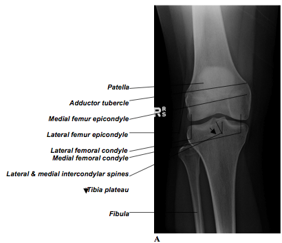
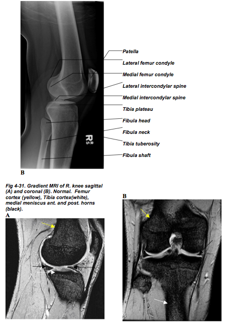
For knee studies an AP and a lateral view should be acquired (Fig 4-30). Sometimes AP standing and/or oblique views are included. MRI of the knee joint is indicated for evaluation of soft tissue injury at the knee joint (Fig 4-31).
The Hip and Femur #
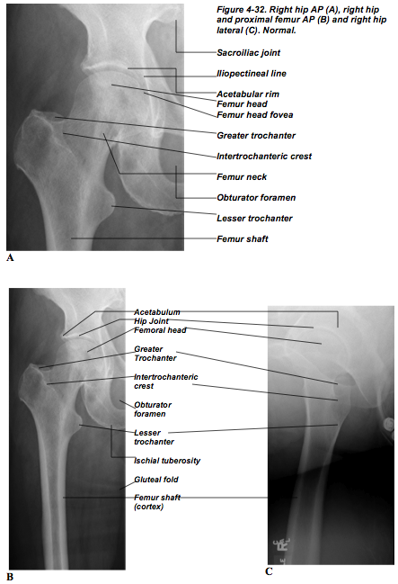
The femur and the hip joint are usually viewed in the same radiograph and this includes AP and lateral views (Fig 4-32).
Trauma – Fracture Evaluation #
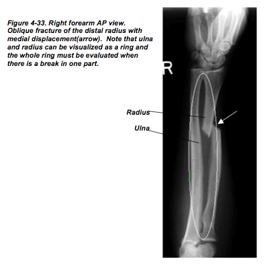
As we mentioned earlier, when you have high clinical suspicion of a fracture, always get at least two views of the bone(s) or joint that are 90 degrees to each other (orthogonal). In the section on ‘normal anatomy’ we covered all the standard projections of the different bones. And in fact these are the views you need in order to confidently rule in/out a fracture diagnosis. Just remember one important point: never accept just one view of a bone or joint. Furthermore, the radiograph(s) that you request should include in them views of the joints immediately above and below the fracture. For example, if there is fracture of the proximal ulna or radius then we might suspect that there is a good chance that there was a second break or dislocation at the distal articulation of the ulna and radius at the wrist. This is sometimes called the ‘ring phenomenon’. That is one can think of the ulna and radius and the two proximal and distal articulation as a making a ring and if there is a break at one location in the ring then there is a good chance that there is a second break in the ring somewhere else. Hence, the need the fully evaluate the bone in question and the proximal and distal joints (Fig 4-33).
As a rule you should apply the ‘ring phenomenon’ to fractures of the humerus, femur, and tibia/fibula.
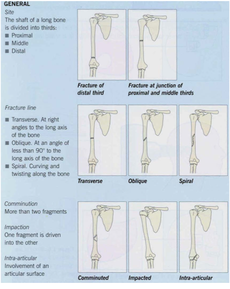
When evaluating a fracture on a radiograph there are four essential pieces of information that you must obtain to describe the fracture.
1. Fracture pattern
2. Anatomic site
3. Alignment
4. Associated soft tissue injuries
Fracture Pattern #
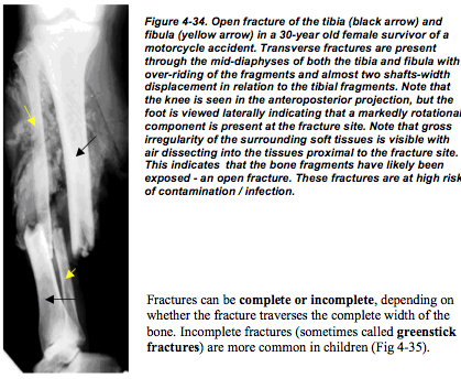
In general, we can break fractures into two clinical categories: simple and compound. Simple fractures are also referred to as closed fractures and it signifies that there is a bone fracture and the skin is intact. The compound or open fracture refers to a situation where there is a fracture in the bone and the skin near it is not intact (Fig 4-34). That is to say the skin is penetrated by the one or more bone fragments or a penetrating foreign body.
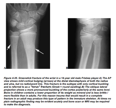
Fracture Types I #
Avulsion fractures are due to the pull of muscles, tendons or ligaments on bone which causes a segment of bone and/or cartilage to be pulled off (Fig 4-36).
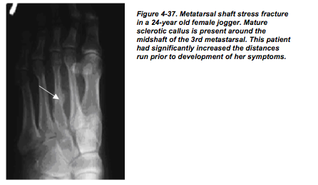
Stress fractures occur due to repeated trauma to normal bone unaccustomed to the type of stress being inflicted on it. Put another way, stress fractures are a result of excess stress on the bone; for example, runners who tend to overdo it (Fig 4-37).
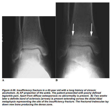
Insufficiency fractures are due to normal stresses and strains placed on bone which is diffusely abnormal (ie. osteoporosis) (Fig 4-38).
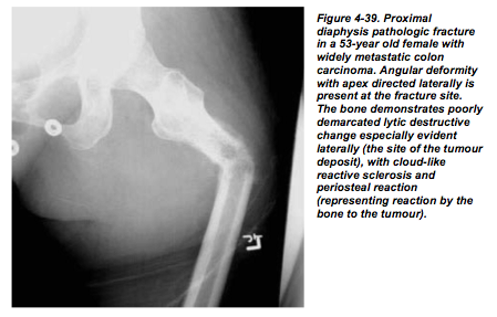
Pathologic fractures (insufficiency fracture can be considered a subtype) occur in bone weakened by a focal abnormality such as a primary bone tumor, metastasis, or a bone cyst (Fig 4-39). These fractures may occur after minimal trauma as well.
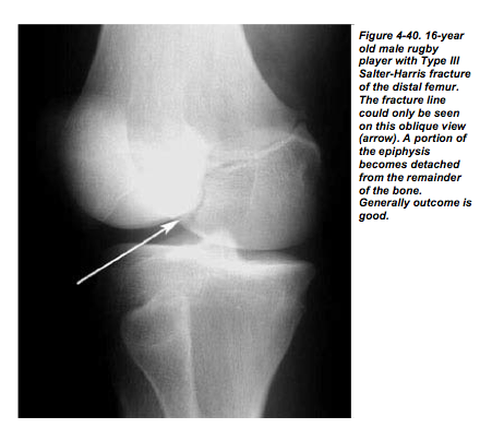
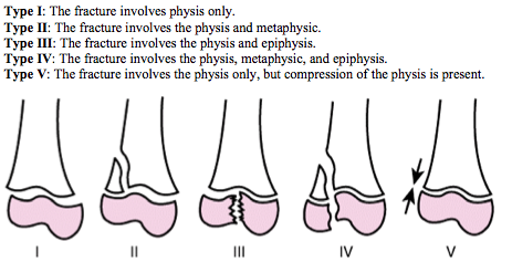
Epiphysial fractures form a separate group encountered in the immature skeleton as the epiphysis constitutes a relative weak point in the bone. The fractures are described in terms of the relationship to the growth plate using the Salter-Harris classification (Fig 4- 40).
Fracture Types II #
Simple transverse fracture involves two bone fragments and the fracture line is perpendicular to the long axis of the bone.
Comminuted fracture is one that results in more than two fracture fragments.
Oblique fracture makes an oblique angle to the long axis of the bone.
Spiral fracture is a severe oblique fracture where the plane of the fracture rotates along the long axis of the bone.
Longitudinal fracture is nearly parallel to the long axis of the bone. It can be though of as a longer oblique fracture.
Impacted fractures occur when the end of a bone is driven into the contiguous metaphyseal region and there is no displacement.
Depressed fracture is an impacted fracture that involves the articular surface of a bone and this often results in joint incongruity.
Anatomic Site #
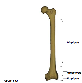
Here is where sound knowledge of your anatomy comes in handy. You should be able to name the bone or bones involved in the injury. Long bones are typically divided into three zones: epiphysis, metaphysis and diaphysis (Fig 4-42). Fractures should be described as involving one or more of these segments (Fig 4-41). You must also specify whether or not there has been intra- or extra-articular involvement.
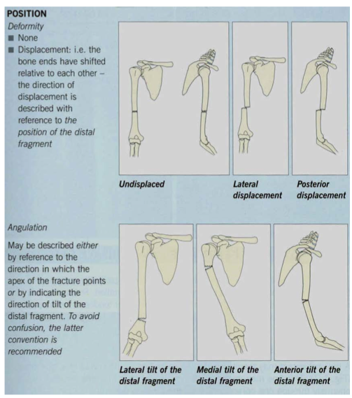
Allignment #
The characteristics to keep in mind when describing the alignment of fractures are:
angulations, rotation, length discrepancy, and displacement.
Displacement
The accepted convention is description of the more distal fragment in relation to the
proximal fragment (i.e. displacement anterior, lateral, and posterior, etc.). The severity of
displacement of the fracture should also be denoted. This can either be done in terms of
direct measurement (i.e. millimeters), or in terms of shaft width (i.e. one-half shaft’s
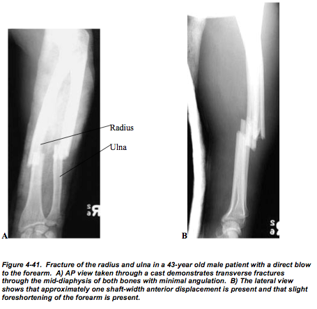
width anterior displacement). Figure 4-41 is a good example of approximately one shaft
width anterior displacement of both the radius and ulna.
Angulations
Fracture fragments are described in terms of their angular relationship to one another.
Fractures will often be described by the direction in which the distal fragment deviates.
Varus is referred to as a tilt towards the midline of the bone beyond a joint or fracture
site, while valgus refers to lateral deviation of the distal part. These terms are often
confusing although they will frequently be encountered when reading the literature. To
avoid confusion it is often simpler to describe the fracture angulations in terms of the
direction of the apex of the angle formed (i.e. apex directed anterior and laterally).
Rotation
Again, rotation is described according to the direction in which the distal fragment moves
(rotates). The degree of the rotational deformity around the longitudinal axis can be
difficult to define without rotation including the joints proximal and distal to the fracture
on the film. At times, specialized techniques are required to evaluate this rotation.
Length discrepancy
Apposition refers to the relationship of the fracture ends to one another. The ends of the
fractures may be completely or partially abutted against one another. Occasionally, the
fracture fragments may actually overlap resulting in shortening of the extremity. Fracture
fragments can be distracted due to muscle pull or the interposition of soft tissues between
the fragments.
Fracture Healing #
Once a fracture has been diagnosed, the next step is to determine whether the fracture
should be allowed to heal in its current position or whether reduction of the fracture is
required by either external or internal means. The degree of acceptable alignment of the
fracture will vary depending on numerous clinical factors including the site of the
fracture as well as patient’s age, type of fracture, nutritional status, adequacy with which
the involved area was immobilized, and presence or absence of infection. Keep in mind
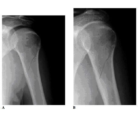
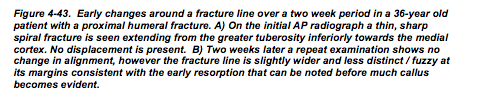
that a few days after the fracture occurs, there may be some absorption of bone as part of
the body’s repair process. Therefore, sometimes fractures are not clearly visible on
radiographs initially but after a week they become clearly visible (Fig 4-43).
When a fracture occurs there may be some hemorrhage into the fracture site. If this is the
case there will be subsequent hematoma formation in between the fracture fragments.
After a few days, bone matrix (osteoid) begins to get lied down in the area. This tissue is
now called a soft callus and you should take note that the soft callus is radiographically
silent. The soft callus then calcifies into a callus that is dense and can be visualized on a
radiograph. As the callus solidifies the bones at the fracture site begin to unite.
Sequelae After Fracture #
ACUTE The fracture lines are usually clearly defined and accompanied by soft tissue
swelling (Fig 4-43A).
SUBACUTE As the hematoma around the fracture organizes, soft tissue swelling will
decrease and bony repair begins. One of the first radiographic changes noted is widening
of the fracture lines in many instances as the dead bone around the fracture lines becomes
reabsorbed. The fracture lines often become slightly hazier and more indistinct at about a
week to two weeks later (Fig 4-43B). Subsequent to this, callus can be identified as a
faint increase in density in the soft tissues adjacent to the fracture line as new mineralized
bone is laid down. This process typically takes longer in older individuals. Motion at the
fracture site increases the formation of callus.
CHRONIC As the callus matures, its outer margins become increasingly distinct and
eventually the callus will fuse with the underlying bone to produce bony union between
the fragments. Callus can also form at the inner surface of the bone, so-called endosteal
callus. This is usually less extensive and more difficult to appreciate radiographically.
Over time the callus gradually becomes remodeled and in some individuals relatively
little deformity at the site of the fracture may be apparent several years later.
The normal time to healing of a fracture will vary depending on the site, the type of
fracture and the patient’s age. Serial radiographs are usually obtained in order to ensure
that healing is progressing satisfactorily and that no changes in position or other
complications occur.
Abnormalities of Fracture Healing #
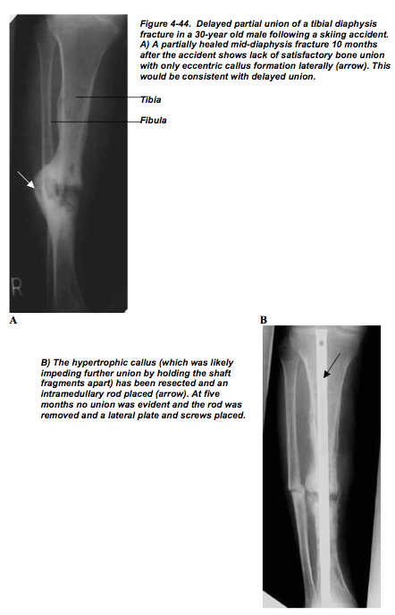
DELAYED UNION The fracture fragments do not unite in the expected time.
Radiographically this is manifested as a persistent fracture and there may be resorption of
bone at the fracture ends. Little or no callus formation may be observed (Fig 4-44A).
NONUNION The fragments show no evidence of union long after the expected time and
no evidence of any progression of healing are noted on serial examinations. Typically this
is manifested radiographically as a persistent fracture line without callus. In some cases,
considerable sclerosis may occur at the fracture ends as they rub against one another (Fig 4-44B).
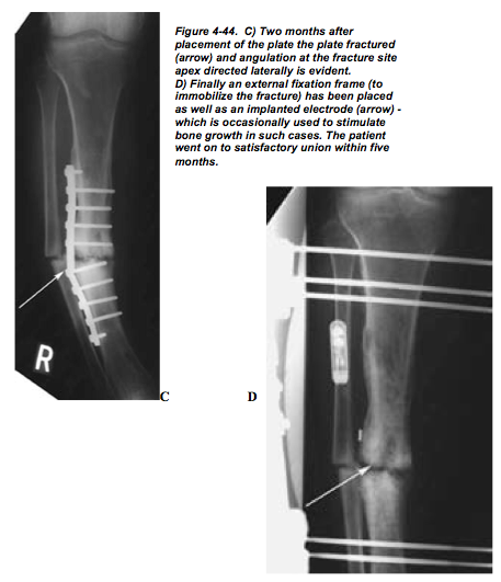
MALUNION The fracture heals but in an abnormal, non-anatomic configuration which
may have undesirable clinical sequelae (Fig 4-45).

Soft Tissue Injuries and Dislocations #
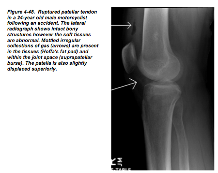
It is important to remember to search for soft tissue abnormalities as even in the absence
of a fracture the presence of a significant injury can be detected. Many dislocations will
occur without an accompanying fracture (Fig 4-48).
ROTATOR CUFF TEARS The rotator cuff is an anatomical term that describes a group of muscles and their tendons that act to stabilize the shoulder. These muscles arise medially from the scapula and connect laterally to the humeral head and in doing so the form a cuff around the glenohumeral joint. These four muscles are the supraspinatus,
infraspinatus, teres minor and subscapularis.
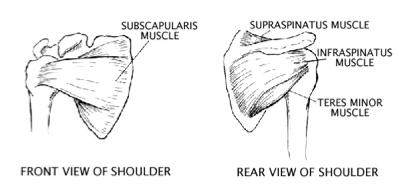
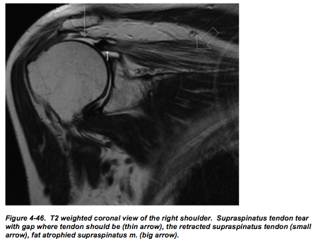
Rotator cuff tears are usually either do to repetitive microtrauma that results from impingement or acute trauma. The supraspinatus tendon is usually the one that is most
commonly torn (Fig 4-46). MRI is very sensitive for complete and partial tears. To
increase the accuracy, MRI arthrography can be performed with the injection of contrast
into the joint space. On MRI look for increased signal intensity or a gap in the muscle at
the musculotendinous junction.
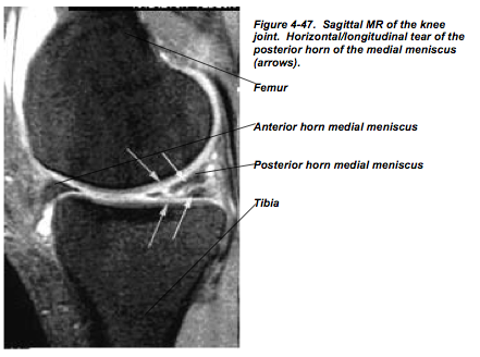
MENISCAL TEARS The medial meniscus is the one that is most frequently afflicted
with injury (Fig 4-47). This is in part due to the fact that in medial meniscus is less
mobile. There are three different patterns of meniscal tears: Longitudinal (vertical) tears
are the most common and are secondary to acute trauma, Horizontal (cleavage) tears are
secondary to degenerative changes and occur more commonly in the elderly, Radial
(oblique) tears. Again, the imaging modality of choice for meniscal evaluation is MRI.
On MR images inspect the menisci for size and shape. On the sagittal recreation the
anterior and posterior horns of the meniscus appear as a “bow tie” that is joint by the
body. The anterior and posterior horns of the lateral meniscus are usually symmetric.
The anterior horn of the medial meniscus, however, is smaller than the posterior horn.
Shoulder Fractures #
CLAVICULAR FRACTURE These are by far the most common fractures you will
encounter in the shoulder area. The distal fragment is usually displaced caudally and
medially in relation to the proximal fragment. The frequency of clavicular fractures by
location is as follows: 80% middle third, 15% distal third and 5% proximal third.
SCAPULAR FRACTURE Very seldom do scapular fractures occur by themselves.
Usually, other thoracic injuries precipitate scapular fractures. Scapular fractures are very
difficult fractures to diagnose.
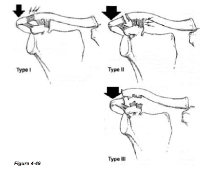
ACROMIOCLAVICULAR SPRAINS This is a true synovial joint with a capsule and an intra-articular disc. This joint is stabilized by numerous ligaments. The coracoclavicular ligament connecting the coracoid process of the scapula and distal clavicle helps stabilize this articulation. Disruption of this joint often occurs with a fall directly onto the joint.
Depending on the degree of disruption of the acromioclavicular ligaments, radiographs in the AP projection may demonstrate inferior displacement of the acromion in relation to the distal end of the clavicle. In questionable cases, this is better demonstrated byweight-bearing views where the patient holds weights in the hands thereby accentuating
demonstration of the disruption.
Acromioclavicular separations are classified according to the position of the clavicle and
injury to the acromioclavicular and coracoclavicular ligaments (Fig 4-49).
Type I: The acromioclavicular ligament is partially torn but there is no displacement.
Type II: The acromioclavicular ligament has torn completely and the joint has widened.
Type III: Both the acromioclavicular and coracoclavicular ligaments have been torn and
the respective joints (acromioclavicular and coracoclavicular) have widened.
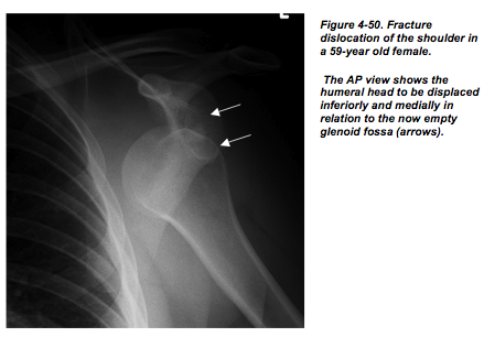
SHOULDER DISLOCATION The humeral head dislocates anteriorly in more than 95%
of cases, with posterior dislocations being rare and often associated with seizures. The
vast majority of dislocations are post-traumatic. Following an initial traumatic
dislocation, instability of the joint often develops and repeat dislocation may occur, even
with minor trauma. The mechanism of dislocation usually involves abduction and
external rotation. With anterior dislocation the humeral head is noted to be abnormally
positioned and displaced inferiorly and medially on anteroposterior radiographs (Fig. 4-
50) and anteriorly on trans-scapular or axillary radiographs
Careful attention should be directed to common sites of associated fractures: the greater tuberosity (Hill-Sachs fracture) as well as to the glenoid rim anteriorly and inferiorly (Bankart fracture). These may not be apparent until post-reduction films of the shoulder are obtained.
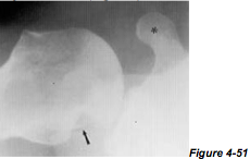
Hill-Sachs fracture occurs when the shoulder is dislocated anteriorly and the posterior humeral head makes contact with the anterior inferior glenoid rim. Hill-Sachs fractures are best appreciated on AP view with internal rotation of the humerus but sometime other views are helpful. Below is an axillary view of the glenoumeral joint demonstrating a hatchet-shaped defect involving the posterior aspect of the humeral head (arrow). Note that the glenohumeral articulation is normal and that the corocoid process (asticks) projects anterior (Fig 4-51).
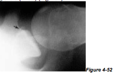
Bankart fracture is best descibed as an avulsion fracture (pull on ligament, tendon, muscle with subsequent bone being pulled off) of the anterior labrum (glenoid fossa), more specificly at the inferior aspect. Bankart fractures are best appreciated on axillary views as can be appraciated below. Note frcature through the anterior rim of the bony
glenoid (arrow) (Fig 4-52).
Other Identifiable Fractures/Conditions #
These are 10 Specific Injuries, Fractures, and other Bone Conditions which you may be called upon to recognize from a plain film.
Elbow Dislocation #
Dislocation of the elbow is the third most common type of joint dislocation after the
gleno-humeral joint and finger joints, and occurs most commonly in persons under 25
years of age. About 80% of dislocations occur posteriorly or posterolaterally. Fractures
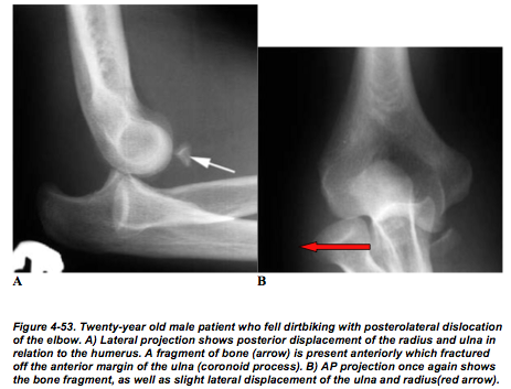
may be associated, especially involving the coronoid process of the ulna (Fig 4-53).
Elbow dislocations are described according to the direction taken by the radius, ulna, or both, in relation to the distal head of the humerus. It is important that you critically examine the radiographs for possible radial head, olecranon, or distal humeral fractures in patients with elbow dislocations.
Radial Head Fracture #
This is a particularly common fracture in adults with the majority of cases resulting from
a fall on the out-stretched arm. Radiographic findings are often subtle with the fracture
line often extremely difficult to detect. An important tip-off to the presence of the
fracture is detection of an elbow joint effusion and displacement of the fat pads of the
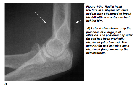
elbow seen on a lateral radiograph (Fig 4-54).
The posterior fat pad and signs are sensitive radiological clues that you can look for in the detection of elbow fractures. On a lateral view radiograph of a normal elbow you cannot see the posterior fat pad, however, adjacent to the anterior surface of the supracondylar humerus you can detect a triangular area of radiolucency which is the anterior fat pad (see ‘normal anatomy’: elbow Fig 4-23). When the elbow is fractured some bleeding into the joint space can occur (hemarthrosis). The blood in the joint space distends the joint capsule to the point that the posterior fat pad becomes visible and the anterior fat pad is lifted off of the bone giving it the appearance of a sail.

As mentioned earlier, however, the fracture will become more evident several days later, after resorption along the fracture line has occurred (Fig 4-55).
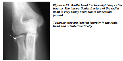
Remember, radial head fractures are very easily missed on plain films especially when
they are non-displaced so always look for the fat pad sign. If you cannot reach a
definitive diagnosis on plain film you may consider radial head view CT.
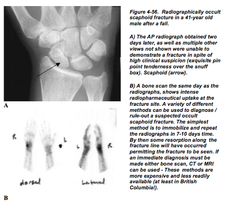
Scaphoid Fractures #
Fractures of the carpal scaphoid are the most common type of carpal bone fracture. Patients typically present after a fall on the outstretched hand and clinical symptoms include tenderness in the anatomic snuff box. These fractures are often difficult to diagnose and are prone to significant complications (Fig 4-56). The area on the dorsum of the hand, just between extensor indices and extensor pollicis tendon, is called the “snuff box”. And the snuff box lies right over the scaphoid. When you encounter a patient who has snuff box tenderness but the radiographs are negative, do not send them away. You can assume that the scaphoid is fractured and the patient should be immobilized and followed up accordingly.
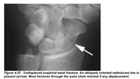
The most common site of fracture is through the scaphoid waist (Fig 4-57).
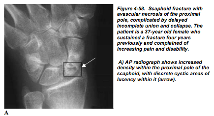
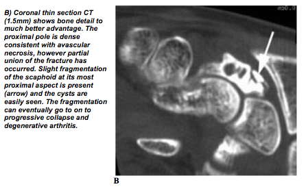
Because blood vessels enter the scaphoid at its distal pole, the proximal pole of the scaphoid will often lose its entire blood supply. This may result in a situation known as avascular necrosis (bone death secondary to loss of blood supply). The more proximal the fracture occurs in the scaphoid the more likely this is to occur. Often multiple views are required in order to detect these fractures as they are seldom significantly displaced. Should avascular necrosis occur, union of the fracture will be delayed or the proximal fragment may collapse and secondary osteoarthritis may become established (Fig 4-58).
When you evaluate radiographs of the wrist make sure that you fully appreciate this relationship. In particular, look for the concave surface of the lunate and make sure the apple (capitate) is in fact resting in there.
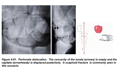
Perilunate dislocation, where the lunate will be in good alignment with the radius (cup and plate) and the other carpals are displaced dorsally (Fig 4-61)
Rotary subluxation of the scaphoid which presents with scapholunate dissociation.
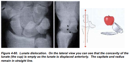
Lunate dislocation where the lunate is displaced in the anterior direction (Fig 4-60).
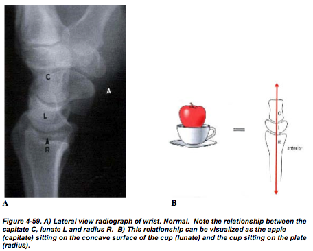
When you evaluate radiographs of the wrist make sure that you fully appreciate this relationship. In particular, look for the concave surface of the lunate and make sure the apple (capitate) is in fact resting in there.
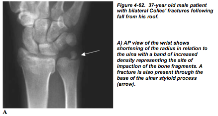
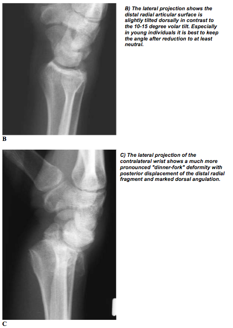
Colle’s Fracture #
This fracture is particularly frequently encountered in older individuals who fall on the out-stretched hand and present clinically with a “dinner fork” deformity. This fracture occurs through the distal metaphysis and epiphysis of the radius. The fracture will often extend into the joint surface. Normally the articular surface of the radius is tilted volarly; however, with Colles’ fracture the articular surface is often angled dorsally and may also be displaced. An accompanying fracture of the ulnar styloid process is almost invariably present (Fig 4-62).
Upper Extremities (hand)
Hip Fracture #
This group of fractures is particularly common in the elderly and is a major source of
morbidity. Diagnosis is usually readily achieved with AP and lateral views, although at
times diagnosis can be very challenging when the fracture is un-displaced (Fig 4-63).
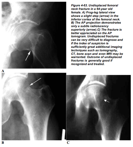
Discontinuity of the cortex and trabeculae are the principle radiographic features.
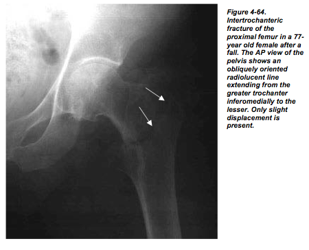
Fracture usually occurs through the femoral neck, but fractures extending through the
intertrochanteric region are common and the lesser trochanter is often broken off as a
separate fragment (Fig 4-64).
The femoral shaft is frequently displaced superiorly in relation to the femoral head, which
is often rotated within the acetabulum but rarely dislocated.
Post-fracture avascular necrosis is common, as the femoral head will lose the majority or
all of its blood supply following a fracture. The majority of the blood supply for the
femur comes distally from intramedullary vessels or from capsular vessels. Both of these
are disrupted following fracture leaving only the relatively minor supply of the artery of
the ligamentum teres.
 #
#
Tibeal Plateau Fracture #
These are often called bumper fractures as a large number of them are associated with a
motor vehicle striking pedestrians, usually from the lateral approach. This produces
impaction of the lateral femoral condyle on the lateral tibial plateau. The tibial plateau
then fractures and is depressed inferiorly. Fat fluid level (lipohemoarthrosis) within the
knee joint due to seepage of marrow fat into the joint space can often be observed (Fig 4- 65).
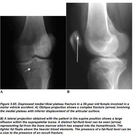
You should be aware that associated femoral fractures may also be present.
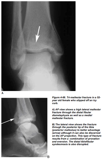
Ankle Fractures #
A large variety of different types of fracture exist involving the ankle joint. The most
common fracture involves the distal fibular diametaphysis, where slight lateral
displacement of the distal fragment is present in association with considerable soft tissue
swelling. Medial malleolar fractures can occur in isolation or in association with a lateral
malleolar fracture. With severe trauma, the posterior lip of the tibia, the so-called
posterior malleolus, may also be fractured and this is usually best demonstrated on lateral
or oblique views (Fig 4-66).
With any type of malleolar fracture, displacement of the talus may occur indicating that
significant ligamentous disruption is also present. An osteochondral fracture of the talus
should always be searched for in this instance, as these are common lesions and may be
highly symptomatic (Fig 4-67).
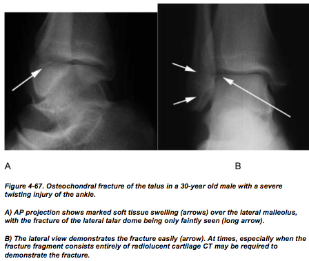
A joint effusion is invariably present in this situation. Although the talar dome is the most
common site of the talar fractures, fractures of the medial and lateral talar processes,
which may be quite tiny, may also be present and be very difficult to detect on plain
films. Fractures through the talar neck (Aviator’s fracture) can occur resulting in
avascular necrosis of the proximal talar fragment.
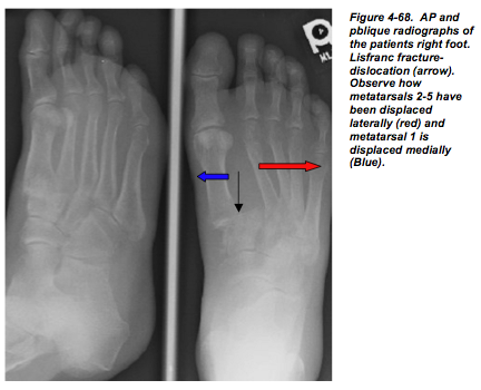
Lisfranc Fracture #
This fracture-dislocation may be radiographically very subtle. The forefoot is dislocated
laterally and dorsally in this condition with the abnormality being particularly evident
medially. The first and second metatarsals are often spread apart. The fracture component
may at times be subtle with only small chip fractures being evident. However, the
significance of this fracture lies in the extensive disruption of the ligaments, especially
the ligament extending from the second metatarsal to the medial cuneiform, which can
cause severe disability. In the absence of discrete trauma, a Lisfranc fracture dislocation
may be a heralding event suggesting a diagnosis of neuropathic foot. As these fractures
may, at times, be subtle, comparison views of the opposite foot may be useful (Fig 4-68).
Osteomyelitis #
Patients with acute osteomyelitis will have increased activity in rapid-sequence perfusion images, blood pool images and delayed images. In acute osteomyelitis bone scan changes can occur a week or more prior to radiographic changes. Bone scans are particularly helpful in differentiating acute osteomyelitis from cellulitis of adjacent tissues. In chronic osteomyelitis the perfusion and blood pool images may not show increased activity. It may be difficult to differentiate osteomyelitis from post-surgical changes, diabetic arthropathy or non-infected fracture with a Tc-99m MDP bone scan alone. It may be necessary to perform a follow-up bone scan or additional imaging with another radiopharmaceutical such as Ga-67 citrate, In-111 WBCs or Tc-99m HMPAO WBCs. There is mild uptake of Ga-67 citrate in non-infectious bone and therefore the increased radiogallium accumulation must be compared with Tc-99m MDP images.
Bone Metastasis #
Many primary tumors will metastasize to bone (e.g. breast, prostate, thyroid, renal and
lung cancer). In patients with a diagnosed primary tumor who have pain but normal
radiographs, approximately 30% will have positive bone scans indicating bone
metastasis. Tc-99m MDP bone scanning is the primary imaging examination used to
detect osseous metastasis. It has been repeatedly shown to be more sensitive than plain
radiography for the detection of osteoblastic metastases. Bone scans are sensitive in
detecting osseous abnormalities but solitary abnormalities are nonspecific and after an
abnormality has been detected, radiographs are generally required for a specific
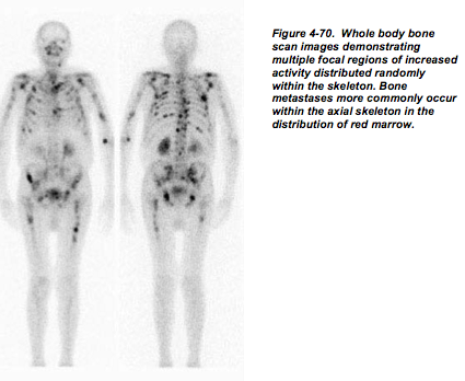
diagnosis. Multiple focal, non-articular regions of increased osseous remodeling within
the axial skeleton are virtually diagnostic of bone metastases. One of the major
advantages of radionuclide bone scanning is that it allows for a total body survey. Bone
scans can also offer a guide to the monitoring of response to therapy (chemotherapy and
radiation therapy). However, in patients who have recently completed therapy bone scans
may be misleading as patients who respond to cancer therapy may have increased bone
metabolism resulting from healing rather than progression of the metastases. This
phenomenon is called “flare” and is observed frequently in breast and prostate cancer
patients who respond to therapy (and is also present in about 20% of patients who do not
respond to therapy).
Arthritis #
Normal Anatomy of Joints #
Various types of joints are found in the human skeleton including fibrous articulations
(such as the sutures between the flat bones of the skull), cartilaginous joints (such as the
symphysis pubis or intravertebral discs) and synovial joints. In a synovial joint, the bone
surfaces are covered with articular cartilage, and a joint cavity is present which is lined
by a synovial membrane. The fibrous joint capsule is located external to the synovial
membrane, and provides structural support for the joint. Some joints contain intraarticular
discs or menisci which function to reduce friction and stress on the articular
surfaces. Intra-articular discs are found in the knee (meniscus), hip (labrum), shoulder
(labrum) and temporomandibular joint (disc). The joint cavity within a synovial joint
typically contains a small amount of clear, yellow, viscous synovial fluid which functions
to provide nutrition of the articular cartilage and lubrication of the joint surfaces.
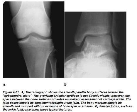
Synovial joints have a number of typical features on plain radiographs (Fig.4-71).
Terminology #
Arthritis– Inflammation of joints.
Arthropathy– An abnormality (nonspecific) of a joint.
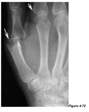
Erosion– A focal bony defect of the subchondral bone usually located at the site of
synovial and capsular attachment to the bone (Fig 4-72).
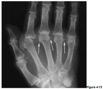
Osteophyte– A bony spur arising at the margin of a joint (Fig.4-73).
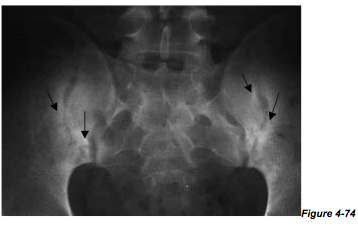
Sclerosis– Focal increased density adjacent to an abnormal joint, producing increased
“whiteness” on the radiograph (Fig.4-74).
Approach to Abmormal Joint Radiology #
A systematic approach to evaluating joint radiographs is necessary to avoid missing
important features. A thorough method of evaluating these radiographs is as simple as
ABCDEs:
• Alignment – subluxations
• Bone proliferation – periosteal reaction, calcification of soft tissues
• Cartilage – joint space narrowing
• Density – bone mineral
• Erosions
• Soft tissue changes
Using this approach, it is possible in most cases to correctly identify the presence of a
joint abnormality and to categorize the abnormality as inflammatory, degenerative,
metabolic or other. Furthermore, you should try to gather information on the distribution
of the abnormal joint(s).
Degenerative Arthritis #
Degenerative arthritis (osteoarthritis) is very common in the elderly population. This
disease is thought to be due primarily to simple mechanical “wear and tear” on the joints
and predominantly affects weight-bearing joints such as the hips, knees and ankles. The
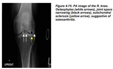
characteristic radiographic features are increased sclerosis of the bony surfaces adjacent to the joint, osteophytes arising at the joint margins, and non-symmetric joint space narrowing (Fig.4-75).
In more severe cases, joint malalignment or intra-articular bony fragments may be seen.
Most cases of osteoarthritis are termed primary, as no underlying cause of the osteoarthritis is evident.
Any disease which damages the joint surfaces may produce secondary osteoarthritis. Clinically, secondary osteoarthritis typically produces joint degeneration which is asymmetric or unusually severe for the patient’s age. The underlying causes which should be considered are previous joint injury (fracture), damage to the cartilage surfaces due to
previous joint infection or inflammatory arthritis, or neuropathic joint.
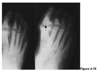
Neuropathic joints occur in patients with decreased sensation, and are most commonly
seen in the feet of diabetic patients. Due to the lack of sensation, the patient repeatedly
traumatizes the joints leading to a very aggressive and advanced form of osteoarthritis.
Neuropathic joints are characterized by marked bony malalignment, destruction and bony
debris. . Clinically, these patients will have minimal symptoms relative to the severity of
the radiographic changes (Fig.4-76).
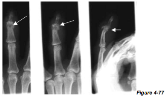
Septic Arthritis #
Joint infection may be caused by direct puncture of the joint or by hematogenous
dissemination of infection. Infected joints typically present with an acute onset of pain,
swelling, warmth, and decreased range of motion. Septic arthritis typically involves only
one joint (monoarthropathy). In the early stages of the disease, the bony structures remain normal. However, if the infection is not treated adequately, the joint surfaces will soon be destroyed (Fig.4-77).
Thus it is critical to make the correct diagnosis promptly. A good rule of thumb is that
any acute monoarthropathy should be assumed to represent an infected joint until proven
otherwise. Aspiration of joint fluid is the most efficient way of establishing the diagnosis.
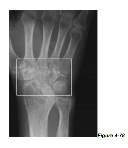
In cases of chronic infection (usually due to TB or fungus), considerable bone
destruction, sclerosis and fragmentation may be seen (Fig.4-78/ SLAC Wrist).
Emergency “Don’t Miss” Findings #
You may have noticed that in this chapter we were not able to include all the various
fractures and pathologies that afflict the musculoskeletal system. What we have done,
however, is give you what we believed you as medical students should be aware of and
be able to recognize radiographically.
In particular, in this section we will reinforce some of the findings that we have already
talked about and that you absolutely must pick up in the emergency.
These finding are:
1. Septic joint (Fig 4-77, 4-78)
2. Fractures with extension into joint (Fig 4-64)
3. Elbow joint effusion, radial head fracture (Fig 4-53, 4-54, 4-55)
4. Shoulder dislocation (Fig 4-50)
Child Abuse #
In this section we will briefly talk about fractures that you may see in cases of child
abuse. However, it is important that you keep in mind that when you see radiographic
evidence of fractures in children that it may be the result of everyday activities. Analyze
the fractures with in the context of the child’ developmental and injury history. For
example, a transverse fracture of the femur in a ten-year-old child maybe unremarkable
but if it is observed in a four-month-old child it is highly suspicious of physical abuse.
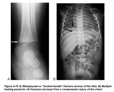
There are certain types of fractures that are highly specific for child abuse. These are:
-metphyseal corner or bucket handle lesions (Fig 4-79 A)
-posterior rib fractures (Fig 4-79 B)
-scapular fractures
-spinous process fractures
-sternal fractures
When you suspect that a child is being abused you should order complete radiographic
survey of the skeleton. The different projections for children are similar to those
acquired for adults and were described in the section on ‘normal anatomy’.