Description #
The use of bedside ultrasound by clinicians to guide invasive emergency procedures has been proven to improve success and reduce complications, and is rapidly becoming established as the standard of care.
UGEMP-Advanced provides an opportunity for physicians to acquire and maintain the skills required to perform the following procedures using Ultrasound-guidance:
1. Abcess drainage
2. Subcutaneous Foreign Body localization and removal
3. Arthrocentesis
4. Lumbar Puncture
5. Paracentesis
Learning Objectives #
At the end of the course, the student should be able to know the cognitive aspects and perform the psychomotor aspects of these procedures with the use of ultrasound guidance:
1. Abcess drainage
2. Subcutaneous Foreign Body localization and removal
3. Arthrocentesis
4. Lumbar Puncture
5. Paracentesis
#
Ultrasound Guided Lumbar Puncture
Ultrasound imaging can reduce the risk of failed or traumatic lumbar punctures (LP) and epidural catheterisations, as well as the number of needle insertions and redirections. Ultrasound may be a useful adjunct for these procedures.1 Most clinicians are effective at performing LP’s using surface anatomical landmarks combined with the loss-of-resistance (LOR) technique. However, palpating the necessary landmarks may be ineffective due to obesity, scoliosis or other anatomical variations. Ultrasound also aids in determining the depth of needle insertion which is most helpful in pediatric and obese patients.
We will utilize ultrasound to locate the spinous processes, the inter-process space, the ligamentum flavum and the depth of needle insertion. We will not be watching the needle advance in real-time under ultrasound guidance.
Probe Selection
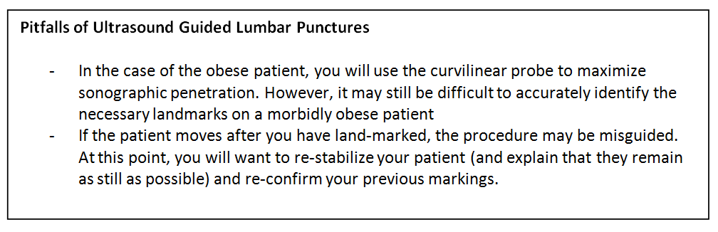
The linear high-frequency probe ( 7-11 MHz) will result in the highest-quality image. However, if you are using ultrasound to locate the spinous process due to patient body habitus, then a curvilinear probe ( 4-7MHz ) will need to be considered. Either will suffice.
Preparation
As this is an advanced ‘land-marking’ technique, a non-sterile approach is sufficient.
Your patient should be seated on the edge of the bed, hunched forward, in order to open up the inter-vertebral spaces. Alternatively, the decubitus patient can curl-up on the bed.
Note 1 : Your patient cannot move once you have performed the land-marking. Patient movement will render the land-marking technique invalid as the structures will have shifted.
Note 2 : if you are checking CSF opening pressure, then the lateral decubitus position is the best and most accurate
Procedure
The probe will be placed at Tuffier’s Line which is a transverse line at the L4-5 level ( approximately the level of the posterior superior iliac crests). The probe orientation marker will be directed to operator left – while it is correct that this is technically the patient’s left side ( and hence the ‘incorrect’ side to point the probe marker), probe movement supersedes the need to have the marker towards the patient’s right (If the probe is ‘backwards’ and facing towards patients right side, all your probe movements will appear as ‘reversed’ on the screen ).
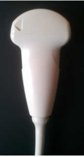
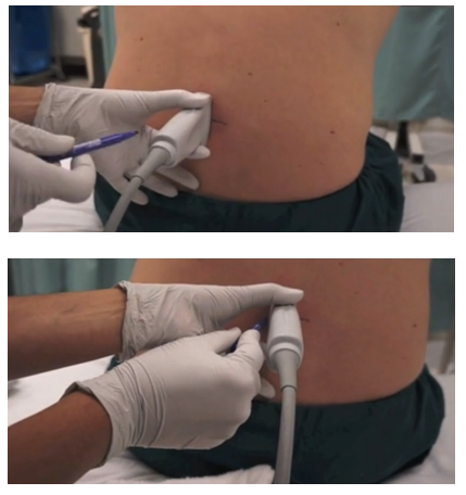
Begin by identifying the spinous process (fig 1). It will be the most superficial bony structure. While the bright/echogenic line of the spinous process may be difficult to identify, the posterior shadow should be very easy to locate. The spinous process itself will usually be only 2-3cm from the top of the screen. Once you have located the spinous process, centre it in the middle of the screen and use a pen to mark the centre of the probe – this will correspond to the midline location of the spinous process
Next, slide the probe slightly cephalad. When the acoustic shadow disappears, you are at the level of the interspace. Continue sliding cephalad until you have located the next spinous process. Centre this on the screen and mark with a pen as done previously.
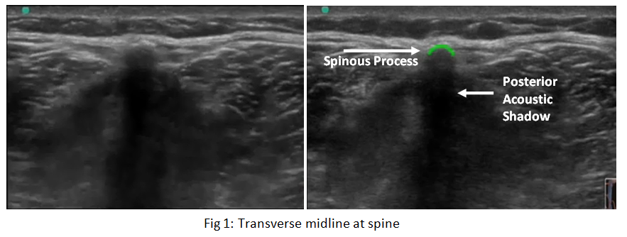
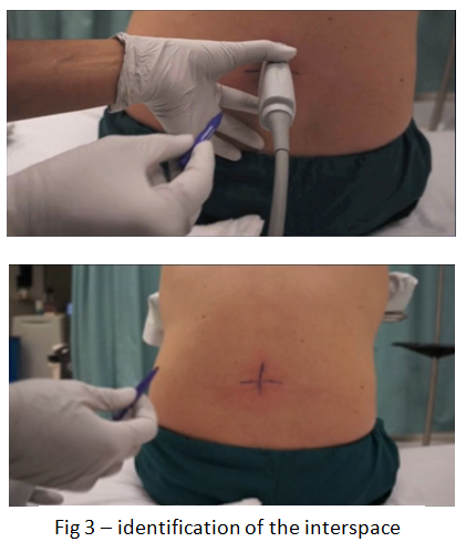
Now rotate the probe into longitudinal with the probe-marker towards the patient’s head and slide the probe slightly caudad so that you are able to visualize both the pre-identified spinous processes (fig 2) . If done correctly, your probe will be lined-up with the pen marks you have made.
Mark the location of the interspace on the patient by moving the probe cephalad and caudad until the interspace is at the centre of the screen – use a pen to mark the centre of the probe on the patient. (Fig 3)
At this point you may want to proceed with LP preparation and sterile drape and begin your procedure. If you have concerns about the depth of the dural sac, continue with the instructions below.
Identification of Dural sac
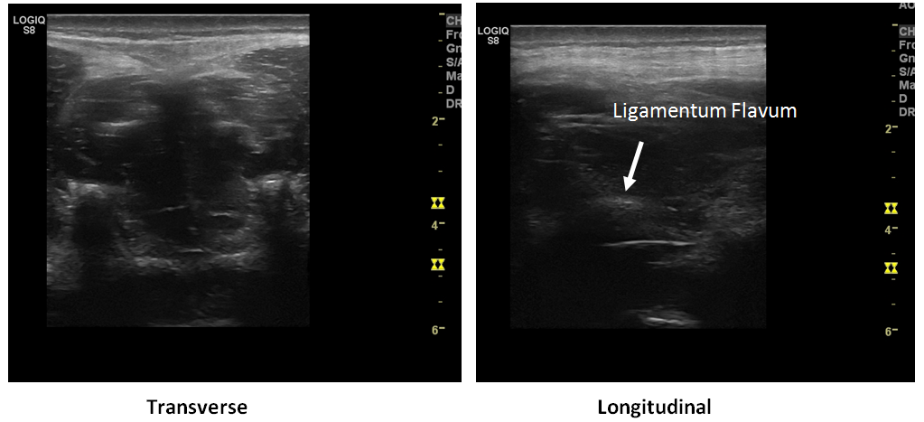
In the case of pediatric patients or the morbidly obese, you may wish to identify the approximate depth to the dural sac in order to avoid advancing the needle too far. Begin by rotating the probe back into a transverse orientation at the level of the interspace. In order to identify the Ligamentum Flavum and dura mater (Fig 4) you may have to angle to probe slightly cephalad by a few degrees. This is due to the downward-facing nature of the spinous processes which you are imaging in-between. Note: The Ligamentum Flavum and Dura Mater structures may appear as a single echogenic line) and determine the necessary needle depth.
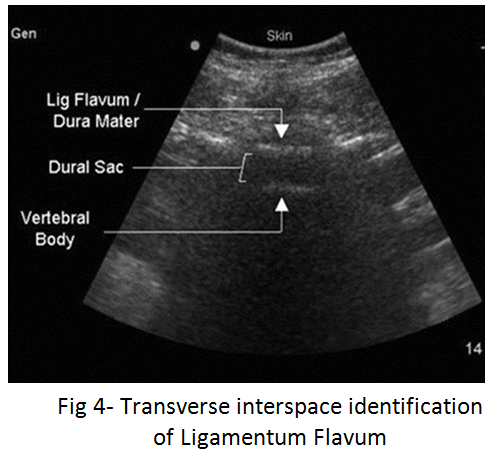
Once you have located the Ligamentum Flavum, freeze the image and measure the distance from the skin to the dural sac.
Shaikh F. et al., Ultrasound imaging for lumbar punctures and epidural
catheterisations: systematic review and meta-analysis. BMJ 2013;346:f1720 doi: 10.1136/bmj.f1720
Dietric, AM, et al. Bedside pediatric emergency evaluation through ultrasonography. Pedeatric Radiology 2008; 38 (4) 5679-94
Peterson, MA. Bedside ultrasound for the difficult lumbar puncture. Journal of emergency medicine 2005; 28(2) p 197-200
Nomura, et al. Randomized controlled trial of u/s -assisted lumbar puncture. Journal of Ultrasound in Medicine. 2007; 26(10) P 1341-8
Conley, et al . Diagnostic and interventional ultrasonography in neonatal and infant lumbar puncture. Pedeatric Radiology 2001; 31(6) p399-402
Introduction to Ultrasound Probes
The ‘art’ of ultrasound is a continuous trade-off between penetration and resolution. The probe can be good at either penetration or resolution, but not both at the same time. Some probes are good at only penetration ( can penetrate very deep into the patient, but resolution is compromised) or only resolution ( the quality of the image is vastly superior, but you are only able to look at very superficial structures ), and some probe walk the line between penetration and resolution by making some compromises to both.
The trick to remember with ultrasound is that you are using sound waves to generate an image. These ultrasound waves are measured in Mega-Hertz ( MHz), with a lower frequency ( 2-5MHz) having good penetration but less-than-ideal resolution. The higher-frequency probes (10-15MHz) have much better resolution, but due to the heightened frequency, are unable to penetrate as far into the body. A good analogy to the ultrasound probes is to think about those ‘pimped-out’ cars where you can hear the stereos from 3 blocks away.
If you think about it, you’re not hearing the full range of the stereo, you are only hearing the base ( low frequency). The lower the frequency, the farther the sound wave can travel. In order to hear the high-end of the stereo, you would actually have to be sitting in the vehicle. This is because high-frequency sound wave cannot travel as far as can lower frequency.
Low Frequency -> travel farther -> “sounds terrible” = decreased resolution
High Frequency -> shorter travel distance -> “clearer sound” = increased resolution
Curvilinear ( 2-5MHz)
This probe is the work-horse of ultrasound. It is a low frequency probe that results in a relatively good amount of penetration. Since the probe is curved, the beam ‘fans’ out through the body, to produce a wide field-of-view. As indicated, this will result in a relative loss of resolution. As the probe is quite large, it is not ideal for fitting into small areas ( such as intercostally for cardiac views )
Phased Array ( 2 – 5 MHz) ( AKA – Cardiac Probe )
This probe also uses a low frequency, but due to the smaller size of the probe-head ( read: smaller ‘foot-print”), it is more useful for fitting into tighter locations, such as intercoastal windows when assessing the heart. The name is derived from the way the computer activates the crystals in the probe – it occurs through “sequential phasing”. Due to the way the crystals are arranged in the probe head, the ‘near field’ is quite small.
Orientation Markers
Every probe in the world will have and indicator marker on them. This marker will ALWAYS be directed towards the patients HEAD (when the probe is in a longidutinal orientation) OR towards the patients RIGHT (when rotated into a transverse orientation ). This marker corresponds to the indicator marker on the screen. If the probe is every orientated the other way, the image will be ‘backwards’ to convention. The probe marker will also become of critical importance in procedures as the needle will be advanced on the same side of the marker, and will therefore always enter from the left side